
The front of the Aircraft Data Card is divided into thirteen areas as shown below. Weapon stations, load capacity and flexible weapons field of fire are on the back of the data card.
 |
|---|
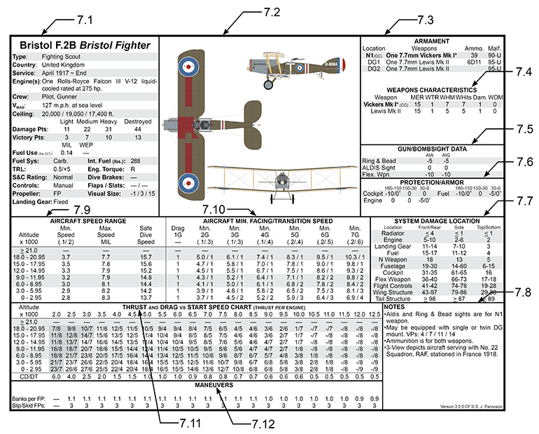
7.0 AIRCRAFT DATA CARD
An Aircraft Data Card (ADC) is used to present the flight characteristics and important data of the airplane in a tabular form. The Aircraft Data Card is divided into thirteen areas as shown below above. The data contained in the ADC is explained as follows:
7.1 Information block
• Aircraft Name – The name and variant designation of the aircraft.
• Type – The type of aircraft and its main combat role.
• Country – The country that produced the aircraft, may not be the country of service.
• Service – The date of introduction and phase out of the aircraft. The phase out date is not an absolute date for removal from service and may not be shown for some aircraft.
• Engine(s) – The number, type and cooling system of engine(s) powering the aircraft. The aircraft are powered by one of four types of engines: In-line, V-Type (V), Rotary or Radial. The cooling system will be either air or liquid-cooled.
• Crew – The number of crew manning the aircraft and their roles.
• VMAX – The maximum speed attainable by the aircraft at the stated altitude.
• Ceiling – The maximum altitude the aircraft is capable of reaching in the Clean, Light, Medium and Heavy Load condition. Only applicable ceilings are listed.
• Damage Points – The number of damage points the aircraft is capable of sustaining. The levels of damage are Light, Medium, Heavy and Destroyed. The aircraft is destroyed when its damage points exceed the Destroyed number of damage points.
• Victory Points – The victory points for each level of damage are listed in this row.
• Fuel Use – Used at the Flight Operations scale and when using the advanced fuel use rules. Lists the pounds of fuel burned per minute at a given speed, MIL and WEP (if applicable).
• Fuel System – The type of fuel delivery system used.
• Int. Fuel – Internal Fuel, the pounds of fuel carried internally by the aircraft.
• TRL: Throttle increment allowable without chance of rough running engine and throttle change modifier.
• Eng. Torque – Notes the direction of torque effect due to engine or propeller rotation. Milti-engine aircraft will have a direction for each engine. For example the Caudron G4 is noted as R / R since both engines rotate to the left and the torque effect is to the right, the opposite direction of rotation. Aircraft with contra-rotating propellers will have opposite torque directions, R / L or L / R would notate a twin engine aircraft with contra-rotating propellers.
• S&C Rating – Stability and Control rating (used in the Advanced Rules). The Stability and Control rating shows how difficult the aircraft is to fly. The S&C Ratings are: Easy (least difficult to fly), Normal, Hard, and Demanding (most difficult). Demanding aircraft require more pilot input and attention, thereby requiring more Task Points to be expended.
• Dive Brakes – Aircraft equipped with dive brakes will be noted with DB-x where x is the maximum amount of drag that may be incurred each game turn the dive brakes are deployed.
• Controls: Type of controls, Manual, Boosted or Flying Tail. Latter are used in The Cutting Edge modules.
• Flaps/Slats – Aircraft equipped with flaps (high lift devices) or slats will be noted in this section. Flap types are Landing Flaps (LF), Combat Flaps (CF), Dive Flaps (DF). Slat types are Automatic (AS), Fixed (FS) or Power (PS).
• Propeller – Type of propeller, fixed pitch (FP) or variable pitch (VP).
• Visual Size Modifier – Three values are noted, Front/Rear, L/R Side, Top/Bottom. DoE and TCE aircraft have radar size.
• Landing Gear – Type of landing gear (LG), fixed or retractable.
7.2 Aircraft 3-View
Shows a top, side and front view of the aircraft. Great effort has been taken to accurately represent the aircraft’s camouflage and unit markings.
7.3 Weapons Data
This section describes the weapons carried by the aircraft as follows:
• Location – Shows the location of the weapon or group of weapons. Weapon locations on the aircraft are coded as follows –
N(x) = Fixed forward firing weapon mounted on the nose of the aircraft. The number of weapons in each N group are noted on the ADC. An aircraft may be armed with more than one N weapon or have different synchronizer/interrupter gear available and is shown by additional N groups. Synchronized weapons are noted in bold text.
W(x) = Fixed forward firing weapons in the wings of the aircraft. An aircraft may be armed with more than one W weapon group and are noted as W1 and W2. Most aircraft have an equal number of left and right weapons to avoid yawing the aircraft due to unbalanced weight of fire. Wing weapons on the same side will be shaded. FR = Fixed rear weapon. Vertical and horizontal arcs are shown in the Fixed Rear Weapon Arc Diagram located on the back side of the data card.
NG = Forward fuselage weapon position, manually aimed
DG = Dorsal weapon, manually aimed.
UW = Upper wing mounted weapons.
VG = Ventral weapon position, manually aimed.
TG = Tail mounted weapon, manually aimed.
RW = Right waist weapon, manually aimed.
LW = Left waist weapon, manually aimed.
Power turrets are noted with a prefix of “P” and “T” in place of the “G”un. For example a dorsal power turret is noted as PDG.
Unless noted otherwise N weapons may be fired individualy or together.
The type of synchronizer/interrupter gear is shown in parentheses. The synchronizer/interrupter type is coded as follows –
AH = Albatros-Hetzke gear
BD = Bullet Deflector gear
CC = Constantinesco-Colley hydraulic system
GS = Gestänge-Steuerung (Fokker) gear
R = Ross gear
S1 = SPAD I gear
S2 = SPAD II gear
SD = Scarff-Dybovsky gear
SK = Sopwith Kauper gear
SL = Semmler
T1 = Nieuport I gear
T2 = Nieuport II gear
VC = Vickers-Challenger gear
ZS = Zentralsteuerung gear
7.4 Weapon Characteristics
Each weapon has its individual characteristics listed in this section. The characteristics listed correspond to a single weapon listed in the Weapon Data section.
• Weapon - Lists the type of weapon.
• MER – Maximum Effective Range, the maximum range the weapon will be able to hit the target and inflict damage. The gun mount, shell ballistics and marksmanship are factors that affect maximum effective range. The maximum range of a weapon is much greater than the effective range.
• WTR – Weapon Trajectory Rating, the vertical drop of the weapon round after it has been fired.
• WHM – Weapon Hit Modifier, represents the effects of rate of fire on hitting a target.
• WHits – The maximum number of hits the weapon is capable of inflicting on the target per game turn.
• Dam. – Damage, the number of damage points inflicted on the target for each hit.
• WDM – Weapon Damage Modifier, the ability of the round to penetrate armor. Used when determining system damage effects.
• Weapon Harmony – Notes the effect of wing and nose weapons on weapon harmony.
7.5 Gun Sight Data
This section gives the gun sight To Hit modifiers and the horizontal arcs in which they apply. The horizontal arcs listed are 90~60, 60~30, and 30~0 degrees with the applicable To Hit modifier listed after each arc.
All fixed forward (FF), upper wing (UW) and defensive guns (DG) are equipped with a Ring and Bead gun sight.
Aircraft may be equipped with other types of gun sights; the dates and die roll required to equip the aircraft with that gun sight are given in the Notes section of the Aircraft Data Card. The available gun sights and their To Hit modifiers are:
7.6 Protection/Armor
This section shows the protection that the engine, armor, and other dense objects on the aircraft provide to the cockpit, engine, fuel, and weapons. The three modifiers listed correspond to the 180~150, 150~30, and 30~0 degree arcs. These arcs are shown outside the circle in Figure 7-4. The modifiers are applied to the system damage die roll when resolving System Hits as explained later in section 31.6 Protection/Armor Modifiers.
7.7 System Damage Location
This lists the system damage locations based on the targets aspect, Front, Side or Top.
7.8 Notes
This section provides the following:
• Lists the equipment and munitions the aircraft could carry
• Gives limitations placed on the weapon mount
• Equipment availability. Some aircraft have different weapons, gun sights, and synchronizer/interrupter gear available to be in service at different times. The equipment the aircraft has is determined by a D10 roll at the beginning of a scenario. The D10 result required for the aircraft's different possible weapons, gun sights, and synchronizer/ interrupter gear are listed in this section.
7.9 Aircraft Speed Range
This block gives the aircraft's minimum (stall) speed, maximum speed, and safe dive speed for each altitude band.
• Altitude x 1000 - Each row corresponds to a band of altitude 2950 feet (899 meters) thick. Use the band containing the aircraft's altitude at the start of a turn to determine these limitations on its speed for that same turn.
• Min. Speed - The minimum speed of the aircraft. At lower speeds, the aircraft will enter a stall and/or spin. The numbers in parentheses are added to the minimum speed when the aircraft is in the Loaded/Max-Load configuration. Refer to the SPAD VII C.1 ADC, 0.1 is added to the stall speed when the aircraft is flown in the Loaded or Max-Load configuration.
• Max. Speed - The maximum speed the aircraft is capable of attaining in level flight.
• Safe Dive Speed - The maximum safe dive speed of the aircraft. At speeds greater than the safe dive speed the aircraft may sustain structural damage and even be destroyed.
7.10 Aircraft Min. Facing/Transition Speed
This section lists the G-Load and the associated minimum speed required to perform a facing change or transition and after the slash, the drag incurred for each facing change or transition. The various G-Loads are shown in the top row and are 2G through 7G. Below the G-Load in parentheses are the loaded and max-loaded minimum speed modifiers. The loaded and max-loaded modifier is added to the minimum speed required to perform a facing change or transition when the aircraft is loaded or max-load respectively. Each column below the G-Load lists the minimum speed required to perform a facing change or transition and the drag points incurred for each facing change or transition in the given altitude band.
7.11 Thrust and Drag Versus Start Speed
This section lists the engine thrust / airframe drag at a given speed for each altitude band. Thrust is a positive and drag is a negative value. The positive and negative signs are not shown on the data card to save space.
“Start Speed” is the speed of the aircraft at the start of the movement phase. CD-DT – Climb Drag and Dive Thrust (CD-DT) shows the amount of thrust or drag the aircraft will incur when gaining or losing each 100-foot altitude increment. The aircraft’s stall speed range has a gray background.
• Banks per FP - Lists the ability of an aircraft to bank. Banking is measured in 30-degree multiples. For each FP it expends, the aircraft can perform the listed number of 30-degree banks. Aircraft equipped with a rotary engine have different bank rates to the left or right depending on the direction of engine rotation.
• Slip/Skid FPs - Lists the flight points the aircraft must expend in order to perform a slip or skid maneuver.